Bore Pumps

Bore Pump Sample Installation
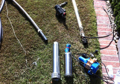
The bore pump chosen is a .55KW Franklin Stainless pump and motor drive. This is set at about 28 metres down the bore hole and above the bottom of the bore hole at 33metres. This is based on information supplied.
Bore Pump Installation and Operation
Plumbing from Pump to Bore Cap
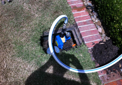
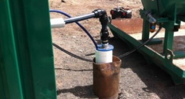
The water is then pumped up through Class 12 Poly for sheer strength. The motor hangs off this pipe so it really has to be good quality. The ends are metric 32mm Poly male iron end connectors.

Bore Pump Sample Installation
Power supply is by rubberised power cable of 1.5-2.5 mm that is suited for long term immersion in water and allows for more secure heat shrink cable connections and safe sealing.
The power cable is taped at reasonable intervals along the poly pipe to keep it tidy.
Non-Return Valve
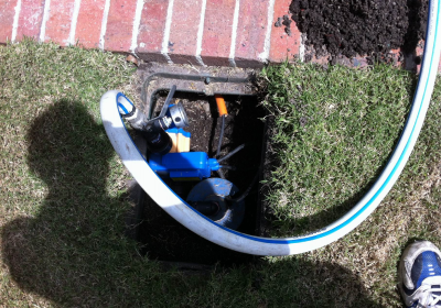
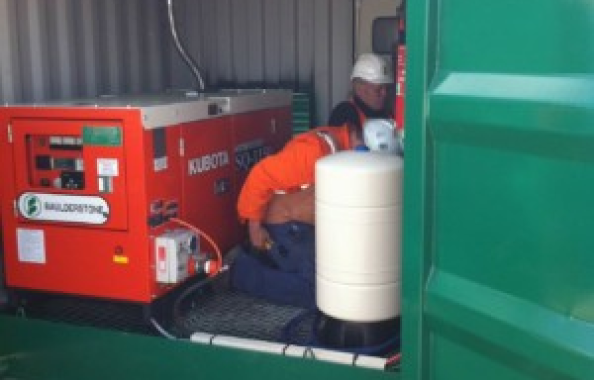
This should be fitted on the output of the poly fittings above the bore cap. Do not use brass non return valves as the bore will likely destroy it quite quickly.
Non-Return Valve
This should be fitted on the output of the poly fittings above the bore cap. Do not use brass non return valves as the bore will likely destroy it quite quickly.
Assembly of Bore Pump

Commissioning
Switch on the power, close over the valve slightly and you should hear the water or the displaced air coming up very quickly. Operate the pump for until steady flow appears and adjust the ball valve and establish nominal pressure and flow. Let it run for a 5 – 10 minutes to enable the water quality to clear. An example of good initial flow is 30 psi at 40 lpm, 40 psi at 55lpm.
Once satisfied that you have clarity and good flow with some pressure, connect to your piping system, whether that is pressured or non pressure. Test the flow for 20 to 30 minutes to allow the system to pump the column of water down to be actually drawing off the aquifer. This will show up by a drop in both pressure and flow. Adjust the valve to create a steady pressure and flow.
Bore Pump Operation – Pressure
The bore pump should now start and stop when you activate the tank ball shut off valve, or
When you open a tap operating off the pressure system.
Bore Pump Operation – Non Pressure
The bore pump flow should shut off and come on when the electric float is raised and lowered in an automatic float system in your water tank.
Variable Speed Drives
There are no settings or adjustments required. You can control flow an increase pressure if desired by closing off the valve on the out which will raise the system pressure.
This is actually recommended to prevent the system surging and where low water production exists.
Keeping the Motor Drive Cool
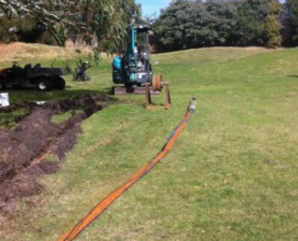
The column of water above the pump should always remain at about 10-15 metres of water above the pump to keep it cool and prevent overheating. Many will operate right down to a few metres above the pump as long as it is steady, but certainly not ideal and can shorten the life of the pump.
Pumps should have a good flow of water being drawn past the motor drive. They should run inside their efficiency curve so that they draw the normal operating current. Once they step outside this they can under draw and over draw.

Shroud Protection - Basic
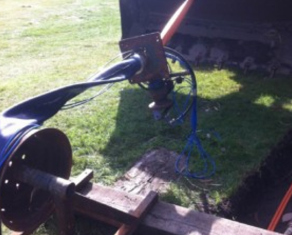
The bore is a low producing bore and needs to have a good FLOW of water supply passing close by the electric motor so that overheating does not occur. We fit a Class 12 PVC plastic shroud to pull the suction flow in quite tightly past the motor and help cool the motor drive.
Simple Run Dry Protection - Ball Valve Control
One other method we employ is to choke the pump output by closing over the valve and causing a backpressure of water inside the pump which is read on a pressure gauge at the bore head.
A good steady pressure reading indicates ample water is sitting above the pump and drawing past.
This prevents air from being drawn with the water over the bore pump drive motor which causes a heat rise and cavitation of the bore pump. Both events being highly undesirable.
Pumptec Controller
The other we recommend where the production of a bore flow is low or the bore is running to maximum is to fit a Pumptec controller. This is a solid state electronic device that can measures a change in temperature and current draw and will shut the pump down as soon as a variation occurs that is potentially damaging to the pump drive.
This indicates that the bore is running too low on water flow or not making water fast enough to keep up with pumping and cooling.
The Pumptec has a built in timer to be set to allow the bore to recover and then re-start the pump. If there is sufficient water made then the pump will start and remain running and if not it will stop again to prevent pump damage.
Franklin VSD Quick Pack Subermisible Drive
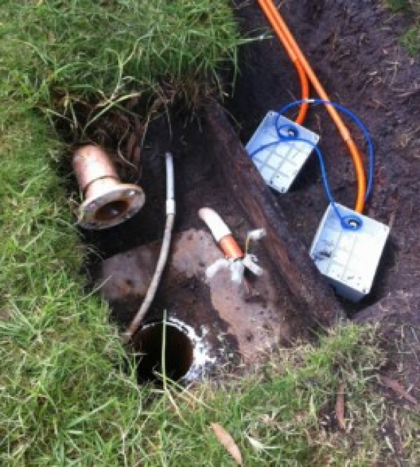
Franklin Electric has produced a variable speed drive quick pack bore control that provides the ultimate protection in the average bore pump.
This VSD system provides the automatic shut down and re-start that a Pumptec controller can do.
The Sub Drive also provides soft starting and a variable speed that provides a far greater flow and pressure performance curves, under and over voltage protection. The motor drive spins from 400-4000rpm to give that wide performance curve that is highly desirable.
The other benefits are that you are getting high performance with very low current draw operation and it is the only time that a bore pump is not over stressed as a pressure system.

Summary
This information sheet is designed as a help aid to newcomers in successfully assembling and installing a bore pump.
Most people purchasing a bore pump have little conception as to what is needed or that it can be so involved.
A properly set up bore pump should last for years once installed and set up and properly.
To obtain a quote please send us:
Water analyses report
Water volume requirement per a day or an hour.
Bore details- Bore depths, water volume, pressures and drawdown level.

